제목 없음


장착법은
L-Clock XO3와 동일합니다. 기존 Clock의 출력전압이 5v가 넘어가는 모델의 경우
D-Clock
기판의 출력선택을
5V로 Setting하셔야 합니다.
| |
| Machine Specific Mounting
Instructions. |
Clock Frequency |
Pioneer PDS 06.
|
16,9344 MHz |
Pioneer PD-S505.
|
16,9344 MHz |
Pioneer PD-S507.
|
16,9344 MHz |
Proceed PCD 2.
|
11,2896 MHz |
Quad 66.
|
11,2896 MHz |
Rega Planet.
|
16,9344 MHz |
Rotel RCD 945
AX.
|
16,9344 MHz |
Rotel RCD 965
BX.
|
11,2896 MHz |
Rotel RCD 970
BX.
|
11,2896 MHz |
Rotel RCD 971.
|
16,9344 MHz |
Rotel RCD 975.
|
11,2896 MHz |
Rotel RCD 991.
|
16,9344 MHz |
Sony CDP 497.
|
22,5792 MHz |
Sony X7 ESD.
|
16,9344 MHz |
Sony CDP X 229
ES.
|
45,158 MHz |
Sony CDP X 303
ES.
|
45,158 MHz |
Sony CDP X 505
ES.
|
45,158 MHz |
Sony CDP X 777
ES.
|
45,158 MHz |
Sony CDP X 779
ES.
|
45,158 MHz |
Sony CDP XA 5
ES.
|
45,158 MHz |
Sony CDP XA 30
ES.
|
45,158 MHz |
Sony CDP XA 50
ES.
|
45,158 MHz |
Sony CDP XB
920.
|
45,158 MHz |
Sony CDP XE 900.
|
45,158 MHz |
Sugden
Optima.
|
11,2896 MHz |
Teac VRDS 10.
|
16,9344 MHz |
Teac VRDS 25.
|
18,432 MHz |
Technics SL-PS
620A.
|
33,8688 MHz |
Technics SL-PS
840.
|
33,8688 MHz |
Thule Spirit.
|
16,9344 MHz |
Yamaha CDX-580
|
16,9344 MHz |
Yamaha CDX-880
|
16,9344 MHz |
Yamaha CDX-590
|
16,9344 MHz |
Yamaha CDX-890
|
16,9344 MHz |
Yamaha CDX-593
|
16,9344 MHz |
Yamaha CDX-893
|
16,9344 MHz |
|
|
| |
Pioneer PDS-06 I TOP I
| Clock Frequency |
16,9344MHz |
| Converter type |
PCM 1702 J |
| Opamps Type |
NJM 2114D |
| Opamp replacements |
AD825 Type 1, 2
pcs. | |
|
| |
 |
Remove the screws holding the top cover, both on the sides, and
on the rear panel. Remove all copper clad screws from right hand located Main
Circuit Board. Also remove the screws holding the plugs to the rear
panel.
Push the CD tray out a bit, by first pushing the smaller of the two
plastic actuator sticks.
Carefully tilt the main Circuit Board out to access
the solder side.
Remove the Oscillator X301, it is located near the inner
corner of the Main Circuit Board.
Connect LClock Out (Red twisted wire) to the solder pad of X301,
nearest W368.
Connect LClock Gnd (Blue twisted wire) to the GND-pad of X301 -
the pad nearest IC61.
Connect LClock +12 V (Red single wire) to W366, about 2
cm. (<1 inch) towards the inner corner of the Circuit
Board.
|
|
| |
 |
|
| |
Pioneer PD-S505
I TOP I
| Clock Frequency |
16,9344MHz |
| Converter type |
PD 2029A |
| Opamps Type |
NJM 4558 (...) |
| Opamp Replacements |
AD825 Type 1, 1
pcs. |
Remove the screws holding
the top cover, both on the sides, and on the rear panel. Remove all copper clad
screws from right hand located Main Circuit Board. Also remove the screws
holding the plugs to the rear panel.
Push the CD tray out a bit, by first
pushing the smaller of the two plastic actuator sticks.
Carefully tilt the
main Circuit Board out to access the solder side.
Remove the crystal unit
'X401' it is found right next to the D/A Converter PD2029A.
Also remove the
two capacitors C403 and C404.
Connect LClock Out (Red twisted wire) to the
solder pad of CNB3, closest to the front panel.
Connect LClock Gnd (Blue
twisted wire) to the solder pad of CNB3, closest to the back panel.
Connect
LClock +12 V (Red single wire) to + terminal on C419, about 2 cm. (<1 inch)
from the back-most corner of the Circuit Board.
Pioneer PD-S507
I TOP I
| Clock Frequency |
16,9344MHz |
| Converter type |
PE8001A (same type as DV-717) |
| Opamps Type |
NJM 4558 (...) |
| Opamp Replacements |
AD825 Type 3, 1
pcs. |
Remove the screws holding the top cover, both on the sides, and
on the rear panel. Remove all copper clad screws from right hand located Main
Circuit Board. Also remove the screws holding the plugs to the rear
panel.
Push the CD tray out a bit, by first pushing the smaller of the two
plastic actuator sticks.
Carefully tilt the main Circuit Board out to access
the solder side.
Remove the crystal unit 'X401' it is found 10cm (4 inches)
in front of the Line Out plugs.
Also remove the two capacitors C403 and C404.
These are Surface Mounted Devices, and best removed by alternating the Soldering
iron, in order to keep both ends melted. Then You can push the component away
from the copper pad, and then pick it up with at tweezer.
Connect LClock Out
(Red twisted wire) to the solder pad of X401, closest to the CD
transport.
Connect LClock Gnd (Blue twisted wire) to the wire link labelled
'GND', right next to X401.
Connect LClock +12 V (Red single wire) to LClock
XO Supply (Required for this model).
Remember to also connect LClock ground
to the XO power supply. Best taken from the minus of the 10.000 uF Capacitor.
| Clock Frequency |
11,2896MHz |
| Converter type |
Burr Brown PCM
58P |
Remove the top cover by
unscrewing the six screws on the bottom side of the enclosure. The Crystal unit
is placed on the vertical sidepanel mounted PCB, on the upper part, near the
rear of the enclosure.
Remove the Crystal unit X400, C402 and
C403.
Connect LClock Out (Red twisted wire) to the pcb solder pad of X400
placed downmost. (Corresponds to pin 11 on SAA7220).
Connect LClock Gnd (Blue
twisted wire) to the pcb solder pad of C402 placed downmost.
Connect LClock
+12V (Red single wire) to CR004, the upmost solder terminal. CR004 is placed
approximately 2 cm. below the Crystal unit.
| Clock Frequency |
11,2896 MHz |
| Converter type |
Philips
TDA1541A |
Remove the two black
screws on the middle of the bottom plate. Remove the screws by both sides under
the bottom plate. Lift the top part away.
Remove the two screws in each side,
holding the back panel. Push the back panel back away from the rest of the
player.
Remove 4 screws, holding the CD transport, of which two are placed
under the CD tray. Look in the hole in each side of the tray, while pushing the
tray out. The two screws will appear when the tray is all out.
Remove the
screws holding the main Circuit Board, also the four holding the mains
transformer, and the one in the corner by the Line out plugs. Last remove the
clips by the 'Open' button.
Unplug the two PCB connectors by the display, now
the entire Main Circuit Board, can be easily removed from the
assembly.
Remove the crystal unit marked '11,2896' it is a shiny metal can
part, found some 10 cm. (4 inches) from the line out plugs.
Also remove the
two surface mounted capacitors connected to the crystal unit on the Solder side.
(There are only the two in question).
Surface Mounted Devices, and best
removed by alternating the Soldering iron, in order to keep both ends melted.
Then You can push the component away from the copper pad, and then pick it up
with at tweezer.
Connect LClock Out (Red twisted wire) to the pcb solder pad
of the crystal unit, closest to the CD transport .
Connect LClock Gnd (Blue
twisted wire) to the wire link at the 'foot end' of SAA7220, closest to the
crystal unit.
Connect LClock +12V (Red single wire) to the 33 Ohms resistor
(orange orange black gold) found very close to the Line Out plugs. Use the
terminal closest to the CD transport.
| Clock Frequency |
16,9344 MHz |
| Converter type |
Burr Brown PCM
1710U |
Remove the screws on the
bottom of the player, and lift the top part gently away from the bottom. Be
careful the tre wires to the lid switch dont come off, they are soldered
directly to the PC Board. Shoul it happen, the red wire goes to +5V, the Black
to Gnd and the Green wire to SIG.
Carefully remove the flex cable to the CD
transport from the socket. Remove screws holding the Main Board, remember the
one in the corner by the mains transformer.
Remove Crystal unit X7, and the
two capacitors marked C2 ( ...? ).
Connect LClock Out (Red twisted wire) to
the pcb solder pad of X7 closest the front of the CD player
enclosure.
Connect LClock Gnd (Blue twisted wire) to the pcb solder pad of C2
closest to the mains transformer.
Connect LClock +12V (Red single wire) to +
on LClock XO Power Supply (Required).
Remember to also connect LClock ground
to the XO power supply. Best taken from the minus of the 10.000 uF Capacitor.
Rotel RCD-945AX
I TOP I
| Clock Frequency |
16,9344 MHz |
| Converter type |
Philips SAA7341GP T |
| Opamps. |
NE 5532 |
| Opamp Replacements |
2 pcs. AD825 module Type
1 |
Remove the top cover, by
unscrewing screws under and at the rear of the enclosure. Also remove the
bacpanel of the enclosure. Loosen the main board by removing all the screws you
can see, looking down on the board, and also the three shiny screws on the
bottom of the enclosure. They hold the CD transport. One of these screws is
located under one of the left side rubber feet.
The main board is now gently
lifted out of the CD player.
Remove the Crystal unit X101, it sits about 20
cm. (8 inches) behind the frontpanel some 10 cm. (4 inches) from the right
sidepanel.
Remove C315, C316 and C317, sitting right next to the
crystal.
Connect LClock Out (Red twisted wire) to the X101 solder pad,
closest to the Back Panel.
Connect LClock Gnd (Blue twiated wire) to the
solder pad of C315, closest to the front panel.
Connect LClock +12 V (Red
single wire) to U104, it is a 78M15 regulator, located behind the CD transport.
Connect to the right hand (output) pin ( when you read the '78M15' text
correctly ).
Rotel RCD-965BX
I TOP I
| Frequency |
11,2896 MHz |
| Converter type |
Philips SAA7323GP
T |
Remove the top cover, by
unscrewing screws on side and rear of the enclosure. Unplug PCB wire connectors
with grey flat-cable, flying across the main board. If You have the discrete
analog extension, this also has to be taken out of the machine.
Loosen the
main board by removing all the screws you can see, looking down on the board,
and also the three black screws on the bottom of the enclosure. They hold the CD
transport. One of these screws is located under one of the left side rubber
feet.
The main board is now gently lifted out of the CD player.
Remove
the Crystal unit X102, it sits about 8 cm. behind the frontpanel some 10 cm.
from the right sidepanel.
Remove C189 and C190, sitting right next to the
crystal.
Connect LClock Out (Red twisted wire) to the X102 solder pad,
closest to the CD transport.
Connect LClock Gnd (Blue twiated wire) to the
solder pad of C190, closest to the front panel.
Connect LClock +12 V (Red
single wire) to U120, it is a 78M12 regulator, located behind the CD transport.
Connect to the right hand (output) pin ( when you read the '78M12' text
correctly ).
Remember to replug the flatcable in the PCB connector, the
connector next to A103 is offset to the right hand side.
Rotel RCD-970BX
I TOP I
| Clock Frequency |
11,2896 MHz |
| Converter type |
Philips TDA 1305
T |
The Crystal unit is mounted
in a rubberbox, on the converter PC Board approximately midway on the PC Board,
a couple of centimeters towards the frontpanel. We recommend NOT using the
rubber box, when fitting LClock. The Converter PC Board is taken out, by
Removing the screws in each corner, and a screw holding the RCA LINE OUT plugs.
Furthermore the metal screen, on the rear panel, is unsoldered from the RCA
plugs. Take the converter PC Board carefully out of the chassis, remove the
Crystal unit ( X301 ). Remove C323 and C324, they are placed right next to the
Crystal unit.
Cut pin 4 on U307 ( 74HCU04 ),
Connect LClock Out (Red
twisted wire) to pin 1 of this IC.
Connect LClock Ground (Blue twisted wire)
to pin 7 of U307 ( 74HCU04 ).
+12V to LClock (Red single wire) is soldered to
J153, it is placed on the other PC Board, next to the heat sink.
As an extra
modification, we can recommend changing the two AD711 in the analog stage, to
AD825 type 4. |
|
| |
|
|
| |
| Clock Frequency |
16,9344 MHz |
| Converter type |
2 pcs. Burr Brown
PCM63/HDCD | |
|
| |


|
Remove top- and bottom cover by unscrewing the (many)
screws.
The Crystal unit is placed in a rubberbox, on the main PC Board right
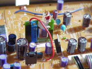
hand side near the front plate. Remove the Crystal unit ( X631 ).
Short
circuit C634 as shown on the photograph. Also break the two PCB traces as shown
on the photo, use Your Dremel or a sharp knife. (Caution!). Short R635 to R634
as shown with the short red wire. |
|
 |
| |
Connect LClock XO Out (Red twisted wire)
to R634, the end closest to the front plate.
Connect LClock XO Ground (Blue
twisted wire) to The PCB GND plane at pin 7-8 of U611, top side of the
PCB.
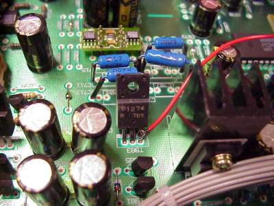
Connect +12V (Single red wire) to T983, use the pin closest to the front
plate.
|
 |
|
| |
 |
Careful not to short other pins with
solder.
You can tune this machine to true high-end performance by changing
the OPA2604's to AD825 modules (type 3, 2 pcs.) And also bypass the DC blocking
Caps (C717 and C718) with a 100n PP (i.e. EVOX-RIFA) and a good quality 100 Ohm
resistor directly to the output plug. Never connect two caps directly in
parallel because of the current resonance problem. |
|
| |
|
|
|
| |
| Clock Frequency |
11,2896 MHz |
| Converter type |
2 pcs. Philips
TDA1305T |
The Crystal unit is
placed in a gummibox, on the converter PC Board approximately midways on the PC
Board, a couple of centimeters towards the frontpanel. We recommend you dont
reuse this rubberthing when installing LClock. The Converter PC Board is
loosened, by Removing the screws in each corner, and a screw holding the RCA
LINE-Out plugs.
Furthermore the metal screen on the rear side, is unsoldered
from the RCA plugs.
Take the converter PC Board carefully out of the chassis,
remove the Crystal unit ( X301 ). Remove C323 and C324, they are placed right
next to the Crystal unit.
Cut pin 4 on U307 ( 74HCU04 ), Connect LClock Out
(Red twisted wire) to pin 1 of this IC.
Connect LClock Ground (Blue twisted
wire) to pin 7 of U307 ( 74HCU04 ).
+12V to LClock (Red single wire) is taken
from J153, placed on the other PC Board, right next to the heat sink.
As an
extra modification, we can recommend changing the two AD711 in the analog stage,
to LT1122.
| Clock Frequency |
16,9344 MHz |
| Converter type |
2 pcs. Burr Brown
PCM63/HDCD |
Remove top- and
bottom cover by unscrewing the (many) screws. The Crystal unit is placed in a
rubberbox, on the main PC Board right hand side near the front plate. Remove the
Crystal unit ( X201 ). Remove C211 and C212, found right next to the Crystal
Unit. Short C212 with a wirebit.
Cut pins 2, 8 and 12 of U206
(74HCU04).
Connect R223, the terminal closest to the CD transport to R204,
the terminal away from the CD transport, and finally pin 11 on U204, using a
short wire.
Connect LClock XO Out (Red twisted wire) to R223, the terminal
closest to the CD transport.
Connect LClock XO Ground (Blue twisted wire) to
pin 7 of U206.
Connect +12V (Single red wire) to + terminal on C909, one of
the large 4700 uF electrolytic capacitors.
| Clock Frequency |
22,5792 MHz |
| Converter type |
SONY CXD
2561 |
The
Crystal unit X327 is placed approximately on the middle of the Main Board.
Remove this Crystal unit, along with C325 and C326, located right next to the
crystal.
Connect LClock Out (Red twisted wire) to the PCB solder pad of the
Crystal unit, closest to the rear panel.
Connect LClock Gnd (Blue twisted
wire) to the PCB solder pad of C326, closest to the rear panel.
Connect
LClock +12V (Red single wire) to JW61, approximately 5 cm in front of the mains
transformer.
| Clock Frequency |
16,9344 MHz |
| Converter type |
Burr Brown PCM
58 |
The Crystal unit is placed
under the bottom cover, remove the bottom cover of the CD enclosure, and gently
take out the PC Board in the CD player enclosure's right hand side. You have to
unscrew the 6 screws holding it.
The Crystal unit is designated X401, remove
it from the PC Board. Connect pin 13 and 14 on the nearby IC 74HCU04.
Remove
the resistor with designator 'OSC', Connect LClock Out (Red twisted wire) to the
PCB solder pad of the 'osc' resistor closest to the 74HCU04.
Connect LClock
Gnd (Blue twisted wire) to pin 7 of IC'a 74HCU04.
Connect LClock +12V (Red
single wire) to IC416, left PCB solder pad, (input), when you read the '7805'
text correctly.
SONY CDP-X229
ES I TOP I
| Clock Frequency |
45,158 MHz |
| Converter type |
Sony CXD 2562
Q |
Remove the top cover of the
CD player enclosure, by Removing the four topscrews and the four
sidescrews.
The Crystal unit is easily located, about 6 cm. behind the RCA
LINE OUT plugs. Unscrew the 4 screws, holding the Main Board, and also the two
screws, holding the LINE plugs on the rear panel. Squeeze the two plastic
fasteners carefully, so the Main Board can be gently lifted out of the CD player
enclosure.
Pull the two flexcables gently out of their sockets, and flip the
PC Board towards the rear panel.
Remove the Crystal unit X331, and the two
capacitors C320 and C321.
Connect LClock Out (Red twisted wire) to the pcb
solder pad of X331, closest to the rear panel.
Connect LClock Gnd (Blue
twisted wire) to the pcb solder pad of C321, furthest away from the CD
transport.
Connect LClock +12 V (Red single wire) to JW112, it is a wire
jumper, placed right next to the largest electrolytic capacitor on the PC Board,
by the rear panel.
Remember to replug the two flex cables!
SONY CDP-X303
ES I TOP I
| Clock Frequency |
45,158 MHz |
| Converter type |
Sony CXD 2562 Q |
| Opamps type |
JRC5532 |
| Opamp Replacements |
AD825 type 1, 6
pcs. |
Remove the top cover of
the CD player enclosure, by Removing the four topscrews and the four
sidescrews.
The Crystal unit is easily located, on the middle of the D/A
Circuit Board in the right side of the CD player.
It is a relatively small
crystal unit, wound in black textile tape. Actually there are two crystals on
this board, but only the one on the middle of the board is to be removed. The
one by the front plate should stay in the circuit.
Loosen the D/A Circuit
Board by removing the three screws on each side. Gently tilt it out of the
enclosure, in order to access the solder side.
Remove the crystal unit 'X621'
and short circuit C621, right next to the crystal unit, now removed.
Remove
L622, found a little towards the front plate.
Connect LClock Out (Red twisted
wire) to the pcb solder pad of L622, closest to the front panel.
Connect
LClock Gnd (Blue twisted wire) to the pcb solder pad of C621, any pin (You just
shorted it, did'nt You?).
Connect LClock +12 V (Red single wire) to IC901, in
the Power Supply, use the pin closest to the CD transport.
SONY CDP-X505
ES I TOP I
| Clock Frequency |
45,158 MHz |
| Converter type |
Sony CXD 2562
Q |
Remove the top cover of the
CD player enclosure, by Removing the four topscrews and the four
sidescrews.
The Crystal unit is easily located, on the middle of the D/A
Circuit Board in the right side of the CD player.
It is a relatively small
crystal unit, wound in black textile tape. It is sitting some 3 cm. (1 inch)
closer to the CD transport, than the big electrolytic Capacitor. Actually there
are two crystals on this board, but only the one on the middle of the board is
to be removed. The one by the front plate should stay in the circuit.
Loosen
the D/A Circuit Board by removing the three screws on each side. Gently tilt it
out of the enclosure, in order to access the solder side.
Remove the crystal
unit 'X602' and the companion caps C627 and C628, right next to the crystal
unit, now removed.
Connect LClock Out (Red twisted wire) to the pcb solder
pad of X602, closest to the front panel.
Connect LClock Gnd (Blue twisted
wire) to the pcb solder pad of C627, furthes away from the CD
transport.
Connect LClock +12 V (Red single wire) to IC405, pin 7.
| Clock Frequency |
45,158 MHz |
| Converter type |
2 pcs. Sony CXD2552
BQ |
Remove the top cover by
unscrewing the 6 screws on the top of the CD player enclosure. Also remove the
bottom plate, by unscrewing the screws.
The Crystal unit is placed on the
converter PC Board, youll find it on the bottom right hand side of the CD player
enclosure. The Crystal unit is placed on the middle in the end of the PC Board
closest to the frontpanel. It is a rather small Crystal, wrapped with black
textile tape.
Remove the converter PC Board by unscrewing the three screws
on each longside of the PC Board.
Remove carefully the Crystal unit X601, and
the capacitors C631 and C632, placed right next to the Crystal unit.
Connect
LClock Out (Red twisted wire) to the X601 PCB solder pad on the converter Board,
closest to the CD player rear panel.
Connect LClock Gnd (Blue twisted wire)
to the PCB solder pad of C632, closest to the rear panel of the CD player
enclosure.
Connect LClock +12V (Red single wire) on the closest (to LClock)
corner of the power supply PC Board. There is two thick red wires going from the
correct terminal on the solder side. On the component side there is a '+15V'
mark.
| Clock Frequency |
45,158 MHz |
| Converter type |
2 stk. Sony
CXD2562 |
This instruction also
applies to a great deal other SONY machines from 1991 to 1996.
Remove the top
cover by unscrewing the 6 screws on the top cover of the CD player
enclosure.
The Crystal unit is placed on the converter PC Board on right hand
side of the CD player enclosure. It is a rather small Crystal unit, wrapped in
black textile tape, you will find it approximately 3 cm. towards the fronpanel
starting by the two large electrolytic capacitors on the middle of the PC Board.
Actually there is two Crystal units on this PC Board, the other one sitting at
the front panel, is used to recreate a nice 16,9 MHz clock to control the CD
transport, but we dont want to tamper with this crystal in the LClock upgrade.
(The slave 16.9 MHz is derived from the precise LClock'ed 45.158 MHz divided by
3).
Remove the converter PC Board by unscrewing the three screws on each side
of the Board.
Carefully unplug the PCB connectors on half of the PC Board,
closest to the front panel. You dont have to worry about the refitting of these
plugs, they only fit together in one way, the right one! Also remove the black
ground wire, screwed right next to the crystal unit.
Remove carefully the
Crystal unit X602, and the capacitors C613 and C614, sitting next to the Crystal
unit.
Connect LClock Out (Red twisted wire) to the X602 solder pad on the
converter PC Board, furthest away from the CD transport.
Connect LClock Gnd
(Blue twisted wire) to the PCB solder pad of C614, closest to the
frontpanel.
Connect LClock +12V (Red single wire) to IC416, left PCB solder
pad, when you can read the text on the component correctly.
SONY CDP-XA 5
ES I TOP I
| Clock Frequency |
45,158 MHz |
| Converter type |
Sony CXD 2562Q / CXA 8042AS |
| Opamp type |
NE5532 / AD712 |
| Opamp Replacements. |
Type 1, totally 4
pcs. |
Remove the top cover, by
unscrewing the 6 black screws on the top. Remove the right hand sidepanel, by
unscrewing the four screws on the outside, and three internally.
The Crystal
unit is placed on the PC Board in the right hand side approximately board
midpoint. Remove the PC Board from the CD player enclosures right hand
side.
The Crystal unit has the designator X602, remove it, along with the two
capacitors C611 and C612
Remove the SMD IC IC604, it is placed right beneath
the Crystal unit, on the solder side. Short circuit pins 6 and 7 of IC604 with a
solder bubble.
Connect LClock Out (Red twisted wire) to X602, the PCB solder
pad closest to the PC Boards right hand edge, when you have a front panel
view.
Connect LClock Gnd (Blue twisted wire) to C611, the PCB solder pad
closest to the PC Boards right hand edge, when you have a front panel
view.
Connect LClock +12V (Red single wire) to JW632, it is a wire jumper,
placed between the two large electrolytic cans on the PC Board.
SONY
CDP-XA30ES I TOP I
| Clock Frequency |
45,158 MHz |
| Converter type |
Sony CXD 2562Q / CXA
8042AS | |
|
| |
|
Remove the top cover, by unscrewing the 4 black screws on the
top, and the 2 on each side.
Remove the supporting metal bar, going from front to rear
panels.
Done by unscrewing the 2
screws by the front and rear.
Drill holes for the LClock XO in this bar, with a distance of 66
mm. (2.60 inch). |
|
| |
This way the XO Clock will hang head down, in the right position
to feed clock signals into the CD player. The original crystal unit 'X321' is to
be found, about midways on the right hand side of the main Circuit
Board.
Remove X321, along with its companoin capacitors C323 and C324.
Connect LClock Out (Red twisted wire) to C323, the PCB solder pad closest to the
CD transport.
Connect LClock Gnd (Blue twisted wire) to C323, the other PCB
solder pad.
Connect LClock +12V (Red single wire) to JW632, it is a wire
jumper, placed between the two large electrolytic cans on the PC
Board. |
|
| |
SONY CDP-XA 50 ES I TOP I
| Clock Frequency |
45,158 MHz |
| Converter type |
Sony CXD 2562Q / CXA 8042AS |
| Opamp type |
OPA 2604 / OPA 2132 |
| Opamp Replacements |
Type 1, totally 4
pcs. |
Remove the top cover, by
unscrewing the 6 black screws on the top. Remove the right hand sidepanel, by
unscrewing the four screws on the outside, and three internally.
The Crystal
unit is placed on the PC Board in the right hand side approximately board
midpoint. Remove the PC Board from the CD player enclosures right hand
side.
The Crystal unit has the designator X602, remove it, along with the two
capacitors C611 and C612
Remove the SMD IC IC604, it is placed right beneath
the Crystal unit, on the solder side. Short circuit pins 6 and 7 of IC604 with a
solder bubble.
Connect LClock Out (Red twisted wire) to X602, the PCB solder
pad closest to R534.
Connect LClock Gnd (Blue twisted wire) to C611, the PCB
solder pad closest to R534.
Connect LClock +12V (Red single wire) to JW633,
it is a wire jumper, placed between the two electrolytic cans on the rear end of
PC Board. (C627 and C628).
SONY
CDP-XB920 I TOP I
| Clock Frequency |
45,158 MHz |
| Converter type |
Sony CXD 8715 / CXA
8355 |
Remove the top
plate by unscrewing the 8 black screws. The original crystal unit 'X301' is to
be found some 10 cm. (4 inches) behind the front panel, at 4 cm. (2 incehs) from
the right hand side panel.
Loosen the Main circuit board, by taking out the
screws holding it, and also the ones holding plugs on the rear panel.
Remove
X301 from the Circuit board, along with its companion caps. C358 and
C359.
Connect LClock Out (Red twisted wire) to X301, the PCB solder pad
furthes away from the CD transport.
Connect LClock Gnd (Blue twisted wire) to
C358, the PCB solder pad closest to the rear panel.
Connect LClock +12V (Red
single wire) to + terminal of C905, one of the big electrolytic cans on the rear
end of PC Board.
SONY
CDP-XE900 I TOP I
| Clock Frequency |
45,158 MHz |
| Converter type |
Sony CXD 8505 / CXA
8055 |
Remove the top cover, by
unscrewing the 8 black screws. The Crystal unit is placed on the main PC Board
approximately 10 cm. behind the frontpanel, and 4 cm. off the PC Boards right
hand edge. Take the PC Board in the CD player enclosures right hand side
out.
The Crystal unit has designator X301, remove it from the PC
Board.
Remove C358 and C359, you will find them right next to the Crystal
unit.
Connect LClock Out (Red twisted wire) to X301, the PCB solder pad
closest to the PC Boards right hand edge, when you hav a front view.
Connect
LClock Gnd (Blue twisted wire) to C358, the PCB solder pad closest to the PC
Boards right hand edge.
Connect LClock +12V (Red single wire) to JW352, it is
a wire jumper, placed on the opposite side of the PC Board, approximately 7 cm.
off the rear panel.
| Clock Frequency |
11,2896 MHz |
| Converter type |
Philips TDA1543 |
| Opamps type |
AD845 |
| Opamp replacements |
AD825 type
4 |
Remove the top plate.
The
original crystal unit '1211' is to be found on the mid Circuit Board, some 6 cm
(2 inches) behind the front panel, and in front of the main processor
module.
Remove Crystal 1211, and the two capacitors placed right next to
it.
Connect LClock Out (Red twisted wire) to 1211, the PCB solder pad
furthest away from the CD transport.
Connect LClock Gnd (Blue twisted wire)
to the PCF2705 IC, pin 8.
Connect LClock +12V (Red single wire) to terminal
+VM, on the opposite side of the same PC Board.
| Clock Frequency |
16,9344 MHz |
| Converter type |
2 pcs. Philips TDA1547 (DAC
7) |
The original Crystal 'X51'
is placed on the rightmost side of the cabinet, about 15 cm. (6 inches) behind
the front panel. Remove X51, and its companion capacitors C51 and C55 (orange
trimmer cap).
Connect LClock Out (Red twisted wire) to the solder pad from
X51, closest to middle of the Circuit Board.
Connect LClock Gnd (Blue twisted
wire) to the solder pad from C51, closest to the edge of the Circuit Board
.
Connect LClock +12 (single red wire) to W221, a wire-link placed on the
opposite side of the circuit board, from the crystal.
Check here for more upgrades to the
VRDS10.
| Clock Frequency |
18,432 MHz |
| Converter type |
4 stk. AD 1862 J-grade |
| Opamps type |
NJM 2114 / M5238 |
| Opamp Replacements |
AD825 Type 2, totally 8
pcs. |
This CD player appears to
be built just right, using all the best parts and techniques possible. However
there are great sound improvements to obtain, by performing the suggested
upgrades.
Remove left top cover. Loosen the Circuit board found inside, by
unscrewing the screws that hold it down, amd also the ones holding the Audio
Plugs to the rear panel.
Short Circuit C101 (some 4 cm - 1,5 inch behind the
AD1893 IC).
Cut L107 off the Circuit Board.
Connect LClock Out (Red
twisted wire) to the solder pad from L107, closest to middle of the Circuit
Board.
Connect LClock Gnd (Blue twisted wire) to the IC U105 (74HCU04), pin
7.
Connect LClock +12 (single red wire) to Cathode of D101, (The terminal
with a marking band) D101 is found right behind the XLR outputs.
Technics
SL-PS620A I TOP I
| Clock Frequency |
33,8688 MHz |
| Converter type |
Technics
MASH |
The Crystal unit X801 is
placed approximately 15 cm. behind the frontpanel, in the right hand side of the
enclosure. Loosen the rear panel, by Removing the three screws along the edge.
Remove screws holding right hand PC Board marked 'AUDIO'.
The Main Board is
taken carefully out of the chassis.
Remove X801, C818 and C819. One of the
PCB solder pads of X801 ( the one closest to the edge of the PC Board ) is
connected to LClock Out. (Red twisted wire).
One of the PCB solder pads of
C818 (the one closest to the front panel) is connected to LClock Gnd. (Blue
twisted wire).
+12V (red single wire) is soldered to J34, placed next to the
optical out unit TX174.
Technics
SL-PS840 I TOP I
| Clock Frequency |
33,8688 MHz |
| Converter type |
Technics
MASH |
The Crystal unit X801 is
placed approximately 10 cm. behind the frontpanel, off the right hand side. The
Main Board is loosened, and taken carefully out of the chassis.
Remove X801,
C835 and C836.
One of the PCB solder pads of X801 ( the one closest to the
middle of the PC Board ) is connected to LClock Out. (Red twisted wire)
One
of the PCB solder pads of C836 (the one closest to the edge of the PC Board) is
connected to LClock Gnd. (Blue twisted wire).
+12V (red single wire) is
soldered to J323, placed on opposite corner of where the Crystal unit was
mounted on the PC Board.
| Clock Frequency |
16,9344 MHz |
| Converter type |
BB PCM 1715U Low Cost V. Out
DAC |
Remove the top cover, Remove the screw holding the converter
PC Board, use a Torx T10 screwdriver. Remove the screw holding the RCA Line Out
plugs. Remove the screw holding the ground wire.
Remove the oscillator X1
(The designator is printed underneath the component...). It is a rectangular
shiny metalcan of approximately 12 by 20 m.m. placed on the converter PC
Board.
Connect LClock Out (Red twisted wire) to the pcb solder pad 'pin 9' on
X1.
Connect LClock Gnd (Blue twisted wire) to the pcb solder pad 'pin 8' on
X1.
Connect LClock +12V (Red single wire) to LClock XO Power Supply +
(Required for this model).
Remember to also connect LClock ground to the XO
power supply. Best taken from the minus of the 10.000 uF Capacitor.
Yamaha CDX-580, 880,590,
890, 593, 893 I TOP
I
| Clock Frequency |
16,9344 MHz |
| Converter type |
YAC 514 |
Begin with removing the top cover, and
next taking the main Circuit board out of the cabinet.
The D/A Converter chip
(Yamaha YAC 517) is placed on the solder side of the circuit board, right
corner, as seen from the front panel side.
Remove the crystal unit XL2,
placed right next to the D/A Converter chip.
Also remove the two cap's C52
and C53, located next to the crystal.
Connect LClock Out (Red twisted wire)
to the solder pad from XL2, closest to the D/A chip and C53.
Connect LClock
Gnd (Blue twisted wire) to the solder pad from C53 furtest away from the
crystal.
Connect LClock +12 (single red wire) to LClock XO Supply + (Required
for this model).
Remember to also connect LClock ground to the XO power
supply. Best taken from the minus of the 10.000 uF Capacitor
|
|
|
